
WiFi Building Materials and RF Attenuation: What a Site Survey Must Prove
Building materials are not background scenery in a WiFi design. They decide where RF energy goes, how much of it remains usable, and whether an access point that looks good on a floor plan will actually serve the clients on the other side of the wall.
The practical question is not whether WiFi can pass through a wall. Sometimes it can. Sometimes it arrives too weak, noisy, or distorted for the work happening on the other side. The better question is: what does this building do to RF, and has anyone checked it under realistic conditions?
Quick answer
Quick answer: WiFi signals can pass through many common materials, but walls, doors, glass, racks, shafts, and occupied rooms can reduce, redirect, scatter, or distort the signal. A professional survey or design validation should confirm what the building actually does instead of relying on generic wall assumptions.
That matters when APs have to cover multiple rooms, cross corridors, reach through conference-room glass, work around metal racks, or serve areas that change as people, inventory, or doors move.
What RF attenuation means in a real building
RF attenuation is the loss of usable signal as WiFi energy travels through or around something. In an open space, the main design problems are distance, antenna behavior, client requirements, and other RF sources. Inside a building, the problem gets physical. The signal is interacting with construction.
On a floor plan, a wall can look like one simple line. In RF terms it may be drywall, glass, masonry, a fire-rated assembly, concrete, metal backing, a utility chase, an elevator core, or a remodel that no longer matches the plan. Two walls that look the same from the hallway can behave very differently.
That is why this Field Note does not publish a generic attenuation-number table. Those tables can be useful as starting assumptions in design software, but they are not a substitute for field validation. The material, thickness, angle, hidden structure, installed equipment, door position, moisture, and occupancy can all change the outcome.
For PacketScout work, material attenuation is treated as a design risk to prove, not a trivia list to memorize.
Materials do more than “weaken signal”
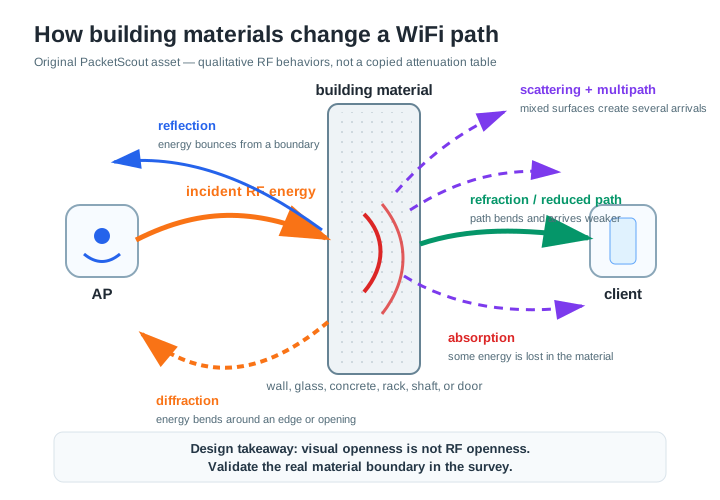
When WiFi meets a building, several RF behaviors can happen at the same time. The exact mix depends on the material and the environment.
Reflection
Hard or conductive surfaces can send RF energy in a different direction instead of letting it continue cleanly forward. Metal doors, racks, machinery, structural steel, elevator areas, and some glass assemblies can all create reflected paths.
Reflection is not automatically bad. WiFi can tolerate some multipath, and in some cases it can use it. Trouble starts when the design assumes a simple, direct path while the building is bouncing energy somewhere else.
Refraction
When RF passes from one material into another, the path can bend. That matters because a straight line drawn from an AP to a client is not always the path the RF energy actually takes through the building.
A wall, glass panel, or other boundary can shift where the signal continues, which means an obstruction that looked “off to the side” on a plan may still affect the real RF path.
Scattering
Rough surfaces, cluttered spaces, inventory, machinery, wet materials, and changing environmental conditions can break a predictable signal path into a messier one. Instead of one clean coverage shape, the building creates pockets of better and worse performance.
This is one reason warehouse, manufacturing, and outdoor-adjacent environments deserve extra attention: the RF environment can change as inventory, equipment, humidity, doors, and loading areas change.
Diffraction
WiFi can bend around some obstructions. This is why a column or partition does not always create a perfect “shadow” with zero signal behind it. Lower-frequency WiFi tends to be more forgiving around obstacles than higher-frequency WiFi, although that does not make it a capacity strategy by itself.
Diffraction helps in many indoor spaces, but it has limits. Large structural barriers, elevator cores, concrete walls, and dense metal environments can still create areas where coverage from the “wrong side” is unreliable.
Absorption
Some materials remove RF energy from the path. Dense construction materials, water-rich contents, people, books, stock, and certain wall assemblies can absorb enough energy to change the design.
This is why an empty building can survey better than the same building on a normal workday. The walls did not change, but the environment did.
Qualitative material-impact guide
Use this table as field guidance, not as a substitute for measurement. The goal is to spot design risks before they become dead zones or unstable client behavior.
| Material or condition | Likely RF behavior | Survey/design implication | Owner page link if applicable |
|---|---|---|---|
| Standard interior drywall or light partitions | Usually the least disruptive common partition, but still introduces some path loss and can hide studs, utilities, insulation, or specialty backing. | Do not assume every similar-looking wall behaves the same. Use it as a baseline, then confirm real client areas on each side. | WiFi site survey services |
| Clear interior glass | Can pass some energy while also reflecting enough energy to create room-edge surprises and multipath near conference rooms or offices. | Treat visually open glass rooms as separate RF zones until measured. Validate seating areas, corners, and door positions. | Office WiFi survey/design |
| Tinted, filmed, laminated, or low-emissivity glass | Often behaves more like a reflective or lossy barrier than ordinary glass, depending on coating and construction. | Flag as higher risk than clear glass. Prefer AP placement that serves the room directly instead of relying on signal through multiple panes. | Office Zoom/Teams Field Note |
| Concrete, masonry, stairwells, and structural cores | Dense or reinforced construction tends to absorb, block, and reflect, creating sharp coverage boundaries. | Survey both sides of the core and plan APs around it. Avoid designs that depend on one AP serving through the core. | Wireless network design services |
| Metal shelving, racks, lockers, cages, or equipment rows | Strong reflection and shadowing; changes in inventory or door positions can change the RF path. | Measure aisle and client locations while the space is operating normally. Place APs for usable work areas instead of clean-looking open air on the map. | Warehouse WiFi design best practices |
| Elevator banks, mechanical rooms, electrical rooms, and shafts | Often combine metal surfaces, dense walls, moving doors, and unpredictable reflections. | Treat as RF boundaries or reflectors, not reliable pass-through paths. Validate lobby/entrance coverage from APs placed in accessible service areas. | WiFi heatmap services |
| Fire-rated doors, security shutters, and service doors | Behavior can change dramatically when the door or shutter is open versus closed. | Capture the normal operating state and the worst credible state. Avoid designs that only work when barriers are open. | Predictive vs onsite survey |
| Water features, aquariums, plants, and dense occupancy | Water-rich objects and people can absorb or reshape coverage in areas that look open on a floor plan. | Validate busy areas and occupied meeting/training spaces. Leave design margin for realistic client density and furniture layout. | What is a WiFi heatmap? |
| Utility chases, pipe clusters, and back-of-house corridors | Mixed materials can scatter and reflect; narrow corridors can appear stronger in one direction than another. | Survey from the client perspective instead of judging from hallway readings alone. Confirm transitions into adjacent rooms. | How to read a WiFi heatmap report |
| Exterior walls, curtain walls, and perimeter glazing | May contain layered glass, insulation, metal framing, concrete, or energy coatings that shape coverage at building edges. | Confirm perimeter rooms separately and avoid using outside-adjacent AP assumptions for interior coverage without measurement. | WiFi site survey services |
The table is qualitative on purpose. Use it to decide what to inspect, what to question, and where to measure.
Why predictive WiFi designs need material validation
Predictive design software is useful when it has the right inputs. The issue is that material inputs are often educated guesses: wall type, door type, glass type, ceiling height, shelving, and construction details may be incomplete or outdated.
A predictive plan can say, “this AP should cover that area,” but the real building can disagree. A wall may have metal reinforcement. A door may normally be closed. A glass room may have treated panels. A warehouse aisle may be full during production even though it was empty during planning. A tenant improvement project may add walls after the original design is approved.
Predictive design still has a place. The assumptions need to be tested when the building or the work is risky. PacketScout covers the survey-type choice here: Predictive vs onsite WiFi survey: which one do you need?. This page has a narrower job: show why material assumptions deserve validation.
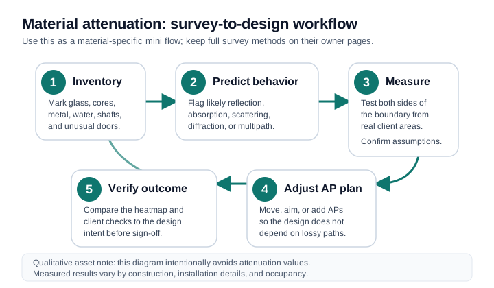
What a professional material-attenuation validation should prove
A useful validation answers practical design questions before anyone trusts the coverage image:
- Which walls, doors, glass areas, racks, shafts, or equipment zones behave like RF boundaries?
- Which areas are being served from the wrong side of a high-impact material?
- Where is the design relying on a hallway, adjacent room, or open door to do too much work?
- Are APs placed on the correct side of the materials that matter?
- Does the network still work when rooms are occupied, doors are closed, and inventory is in its normal state?
- Which construction changes require AP relocation, added APs, antenna changes, or a new validation pass?
The measurement workflow itself belongs in a survey process guide, not in this article. For the collection mechanics, see WiFi site survey data collection best practices. For what should be documented after the work, see What a professional WiFi site survey report should include.
Heatmaps help, but the material story still has to be interpreted
A heatmap can show where coverage changes across walls, rooms, shafts, racks, and doors. It cannot explain the cause by itself.
The interpretation is the useful part: “this wall behaves like a boundary,” “this AP should move inside the served area,” “this glass room needs validation during use,” or “this warehouse aisle cannot be treated like open office space.”
For broader heatmap concepts, use What a WiFi heatmap shows, and what it misses. For report interpretation, use How to read a WiFi heatmap report. If you need PacketScout to perform the analysis, see WiFi Heatmap Services and Wireless Coverage Analysis.
AP placement callouts for material-heavy buildings
Keep concrete and elevator cores out of the coverage plan
If a structural barrier behaves like a boundary, treat it like one. Place APs to serve users from the correct side instead of hoping enough signal leaks through.
Be careful with hallway-only designs
Hallway APs can look efficient on a floor plan, but they often ask RF to cross too many doors, walls, glass panels, or dense rooms before reaching users. A material-aware design places APs for the service area instead of the easiest cable path.
Validate metal environments in their working state
Metal racks, machinery, lifts, shelving, and product can change the RF shape. A warehouse surveyed empty may not represent the warehouse that scanners and tablets use every day. For warehouse-specific design guidance, see Warehouse WiFi design best practices, Warehouse scanner WiFi survey guide, and Why barcode scanners keep dropping WiFi.
Treat glass rooms as real rooms
Glass-heavy offices can look open while behaving like separate RF spaces. Glass type, framing, room density, and meeting-room usage can all matter. For office-specific performance issues, see Office WiFi survey: why good signal still fails Zoom and Teams calls.
Re-check after construction changes
A design validated before walls, doors, racks, or occupancy are final may need another pass. Construction sequencing is one of the easiest ways for a good plan to become a bad install.
On-page capture list before a material-focused survey
You do not need a downloadable worksheet to start gathering useful context. Before a survey or design validation, capture these items in one place:
- Current floor plans or as-built drawings, if available.
- Photos of unusual walls, glass, metal doors, warehouse racks, mechanical rooms, elevator areas, and dense storage.
- Notes on which doors are normally closed, locked, propped open, or only closed after hours.
- Occupancy patterns for classrooms, meeting rooms, event spaces, production floors, and shift changes.
- Areas where users report problems even though the AP looks nearby on a plan.
- Planned construction, tenant improvements, wall additions, rack changes, or equipment moves.
- Service areas where wireless failure disrupts work, such as conference rooms, scanner paths, POS areas, nurse stations, classrooms, or loading docks.
- Known client types that matter to the design, such as laptops, tablets, scanners, phones, carts, or IoT devices.
This context helps the survey focus on real risk instead of walking the building as if every wall is the same.
What this does to performance
When attenuation pushes received signal closer to the surrounding RF floor, clients have less margin for retries, noise, and roaming mistakes. PacketScout covers that theory in WiFi signal strength, SNR, noise, and channel overlap explained.
Where PacketScout fits
PacketScout uses material-aware survey and design work to find the spots where the building is changing the RF plan. That may mean validating an existing WLAN, correcting AP placement, checking a predictive model against the real site, or documenting why a remodel changed performance.
For measurement and validation, see Wireless & WiFi Site Survey Services for Reliable Business Networks. For design work before deployment, see Wireless Network Design Services and Predictive WiFi Planning. For environment-specific service pages, see Warehouse WiFi Survey and Design Services and Office WiFi Survey and Enterprise WLAN Design Services.
Related PacketScout resources
Use these when the question moves outside material attenuation:
- Survey process: How to do a WiFi site survey, WiFi site survey checklist, WiFi site survey data collection best practices, and How to use Ekahau Sidekick for a WiFi survey.
- Survey methods and validation choices: Predictive vs onsite WiFi survey: which one do you need? and AP-on-a-stick WiFi survey: when it helps and when it does not.
- Heatmap and reporting context: What a WiFi heatmap shows, and what it misses, How to read a WiFi heatmap report, and What a professional WiFi site survey report should include.
- Modeling pitfalls: Common Ekahau survey mistakes that create bad WiFi designs.
- Planning scope before engaging a survey: WiFi survey planning tool.
FAQ
Which building materials are usually hardest on WiFi?
Dense structural materials, metal, elevator or mechanical cores, masonry, and water-rich environments are usually higher risk than light interior partitions. The real answer still depends on thickness, construction, angle, nearby objects, occupancy, and the required client experience.
Can a predictive WiFi design account for material attenuation?
Yes, but only as well as the inputs allow. Predictive tools can model wall and material assumptions, but those assumptions should be checked against the real building when the project depends on reliable coverage or capacity.
Should every room get its own access point because walls attenuate WiFi?
No. One AP per room is often unnecessary and can create other design problems. The goal is to place APs where they serve users with enough margin while avoiding unrealistic reliance on high-impact barriers.
Does 6 GHz increase the need for material validation?
Often, yes. Higher-frequency WiFi is generally less forgiving around and through obstacles, so a design that worked acceptably at lower frequencies may still need validation before 6 GHz is treated as production-ready everywhere.
Can a heatmap show material attenuation problems?
A heatmap can show where coverage changes across walls, doors, racks, and rooms. The engineering interpretation matters more than the color: what material caused the shape, whether AP placement should change, and which work areas need reliable service.