
AP Placement and Mounting Constraints in Real Buildings
Wireless Design Note
AP placement is where RF design meets the building: ceiling types, cable paths, service access, aesthetics, safety rules, and real installation windows.
AP placement is a design decision, not just an installation task
The cleanest WiFi designs usually fail in very ordinary places: above hard-lid ceilings, behind decorative soffits, inside mechanical rooms, on the wrong side of rated walls, or in a corridor where the cable path is convenient but the clients are not. A predictive model can show where an access point should work from an RF perspective. A real building decides whether that location can be mounted, powered, cabled, serviced, approved, and kept out of trouble with the owner, architect, safety team, and facilities crew.
That is why AP placement best practices need two lenses. First, ask what the radio cell needs: client density, attenuation, roaming path, band plan, antenna pattern, mounting height, and expected application behavior. Then ask what the building will allow: ceiling type, cable pathway, conduit, access windows, lifts, aesthetics, fire-stopping, plenum rules, weather exposure, tamper risk, and future service access. The best final location is rarely the mathematically perfect point on a drawing. It is the best compromise that preserves the design intent while respecting physical and operational constraints.
PacketScout treats AP placement as part of the WiFi design workflow, not a late-stage hardware detail. If the location cannot be installed cleanly, it is not a real design location yet. For larger or higher-risk projects, that means coordinating AP placement with wireless network design services, field validation, and sometimes an onsite WiFi survey before ceiling tiles are opened or lift time is scheduled.
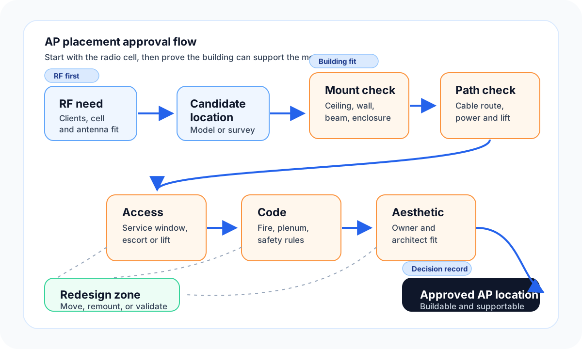
Start with the candidate cell, then qualify the mount
A common mistake is to choose AP locations by walking the building and pointing at places that are easy to reach. That approach often produces a network that is easy to install but hard to use. The better workflow starts with a candidate RF cell and then qualifies the mounting location.
For each candidate AP, ask five questions before it becomes an approved installation point:
- Does the location serve the right clients? Place the AP near the users, devices, and work areas it is meant to support, not merely near a cable closet or convenient hallway.
- Does the antenna pattern match the mount? A ceiling-mount AP above an open office behaves differently from a wall-mounted AP in a corridor or an AP attached to a beam in a high-ceiling space.
- Can the cable path reach it without ugly or unsafe workarounds? A location that requires exposed cabling across finished ceilings, unplanned conduit, or difficult penetrations may need a nearby alternative.
- Can the installer and future technician reach it? If a lift, escort, shutdown window, or ceiling access permit is required, the project schedule and support plan need to know that early.
- Can the building owner approve it? Architecture, tenant standards, safety rules, and security policies can all change the final mounting choice.
This does not mean design should surrender to every constraint. It means each constraint needs a deliberate response. Sometimes the right answer is a different mount. Sometimes it is a different antenna. Sometimes it is a design exception that must be called out before bidding or installation. Sometimes it is a field test, such as an AP-on-a-stick WiFi survey, used only to validate a difficult candidate rather than to replace the broader design process.
Mounting options and when to use them
The table below is written as a design aid, not an installation standard. Final mounting choices still need to follow the AP vendor documentation, local code, site policy, and the authority having jurisdiction. The goal is to identify the constraint early enough that the RF design, cabling plan, and installation plan stay aligned.
| Mounting approach | Works well when | Constraints to confirm | Avoid or redesign when |
|---|---|---|---|
| Ceiling tile or ceiling grid mount | Office, classroom, retail, clinic, and similar spaces with accessible ceilings and clients below the AP. | Grid strength, plenum rating, cable support, tile replacement plan, antenna orientation, ceiling height. | The ceiling is decorative, inaccessible, unusually high, metal-backed, or not approved for visible equipment. |
| Hard-lid ceiling mount | Finished spaces where the AP should remain overhead and visible cabling is not acceptable. | Above-ceiling pathway, junction box or bracket, drilling approval, patching expectations, fire-stop needs. | The location requires destructive work that was not scoped or cannot be serviced later. |
| Wall mount | Corridors, small rooms, exterior walls, utility areas, or sites where ceiling access is limited. | Antenna pattern, mounting height, client direction, cable entry, tamper risk, aesthetics. | The AP would radiate mainly down a hallway while users sit behind walls, shelving, or glass. |
| Beam, strut, or high-bay mount | Open structures, industrial spaces, gyms, warehouses, and large-volume rooms. | Height, antenna selection, lift access, vibration, obstructions, cable protection, future maintenance. | The page objective is general AP placement only; use warehouse-specific guidance for scanner and rack-depth design. |
| Pendant or drop mount | High ceilings where the AP must be lowered closer to the client layer. | Mounting hardware, sway, cable concealment, appearance, collision risk, service access. | The drop becomes visually unacceptable, physically vulnerable, or too low for the space. |
| Enclosure or protective mount | Public areas, outdoor-adjacent spaces, dusty areas, washdown zones, or tamper-prone rooms. | Material attenuation, heat, ventilation, weather rating, locking hardware, service procedure. | The enclosure significantly changes the RF pattern or makes normal maintenance impractical. |
| Aesthetic cover or concealed mount | Hospitality, executive, museum, worship, or high-design spaces. | RF loss through the cover, color/finish approval, label visibility, service access. | Concealment turns a clean RF design into an unpredictable hidden antenna system. |
| Above-ceiling hidden mount | Only when approved and specifically modeled or tested. | Ceiling material loss, plenum suitability, access, code, labeling, service plan. | It is used merely to hide equipment from view without proving RF impact. |
Mobile table note: On narrow screens this table should either scroll horizontally with readable columns or be transformed by scoped CSS into stacked cards using the data labels in each cell. Do not let the columns squeeze into one-letter wrapping.
Constraint one: the ceiling is not neutral
Ceilings are often treated as empty space, but they are part of the RF and installation environment. A suspended acoustic tile ceiling can be convenient for cabling and mounting. A hard-lid ceiling can require pre-planned boxes, anchors, access panels, or conduit. A decorative ceiling can make visible equipment unacceptable. A metal pan ceiling can change how signals reflect and attenuate. A plenum space can impose cable and material requirements that should be handled before installation starts.
The ceiling also affects antenna orientation. Many indoor APs are designed for a typical overhead mounting position. Turning that same AP sideways on a wall or hiding it above ceiling material can change the coverage pattern enough to create weak zones, sticky roaming, or extra co-channel contention. If the only acceptable location forces a nonstandard orientation, the design should call that out instead of assuming the default heatmap remains valid.
The practical rule is simple: do not approve a ceiling location until the ceiling type, access method, cable pathway, and orientation are known. If the building materials are uncertain, link the placement decision back to material attenuation analysis and survey evidence. PacketScout’s note on WiFi building materials and RF attenuation is the better owner for wall, glass, concrete, metal, and ceiling-loss behavior; this Field Note stays focused on the mount decision itself.
Constraint two: aesthetics can move the AP, but should not erase the design
Architectural constraints are real. In hospitality, retail, schools, houses of worship, medical offices, executive spaces, and historic buildings, a visible AP may be treated like a design defect even when it is technically correct. Paint color, device size, label visibility, cabling, conduit, and bracket shape can all become approval issues.
The design response should be structured. First, identify the RF-preferred location. Second, identify acceptable visual zones: near existing technology, aligned with lights or speakers, inside a service band, on a beam, or above a finished line of sight. Third, decide what the deviation does to the wireless cell. A small move within the same room may be harmless. Moving the AP into a corridor because it is less visible can push the cell away from the users and force the signal through more walls. Hiding the AP above a decorative element can introduce unknown loss. Replacing a ceiling mount with a wall mount may require a different antenna model or power plan.
Aesthetic compromise is not the problem. Unmeasured compromise is the problem. If an architect or owner rejects the best RF location, document the alternative, the expected impact, and the validation step. That record prevents the final network from being judged against a design that was never actually allowed to be installed.
Constraint three: access and time windows shape the real project plan
AP placement is also a scheduling problem. Some locations require a lift. Some require after-hours access. Some require union trade coordination, security escorts, infection-control procedures, production shutdowns, retail blackout windows, or school-calendar timing. These are not paperwork details. They determine whether the location can be installed, tested, and maintained without surprising the customer later.
A good design package distinguishes normal mounts from constrained mounts. For example, an office ceiling AP above a standard tile may be simple. An AP above a lobby feature ceiling may require a separate installation window. An AP over a manufacturing line may need downtime coordination. A mount above a secured area may require an escort and chain-of-custody handling for keys or badges. An AP over public seating may need work performed outside business hours.
The support lifecycle matters too. If replacing an AP would require scaffolding or a production shutdown, the design should ask whether a slightly different location can preserve performance while making future service safer. A network that can only be maintained during rare access windows may become expensive even if the initial install succeeds.
Constraint four: code, safety, and facilities rules are design inputs
Wireless designers do not replace licensed trades or code officials, but they do need to design in a way that avoids obvious conflicts. AP locations can touch fire-rated assemblies, plenum spaces, cable support rules, grounding requirements, hazardous areas, emergency egress, sprinkler clearances, ceiling-grid limitations, dust or washdown exposure, and outdoor weather ratings. Even when the AP itself is low-voltage equipment, the way it is mounted and cabled can create compliance work.
The design should identify questions early:
- Does the cable pathway cross a fire-rated wall or floor that must be sealed properly?
- Is the ceiling space used for air handling, requiring approved cable and hardware?
- Will the AP or bracket interfere with sprinklers, signage, lighting, cameras, speakers, or access panels?
- Does the environment require a protective enclosure, outdoor-rated hardware, or special cleaning procedure?
- Are there landlord, tenant, healthcare, education, or industrial rules that constrain device placement?
When those questions are unanswered, the location is provisional. Mark it that way. A mature WLAN design separates RF intent from installation approval so the customer knows which locations are final and which locations need facilities confirmation.
Cross-environment placement callouts
What to document before installation
A placement-ready WLAN design should make the mount decision obvious to the installer and defensible to the customer. At minimum, document the proposed AP identifier, room or area, mounting type, mounting height, orientation, cable pathway assumption, required hardware, access constraints, aesthetic notes, and unresolved approval items. If a location changed because of aesthetics, code, or cabling, record the reason and the expected RF effect.
Photos help. So do annotated floor plans, reflected ceiling plans, and short notes such as “requires lift,” “coordinate with facilities,” “confirm plenum hardware,” “do not move into corridor without redesign,” or “alternate location acceptable within this zone.” The point is not to create paperwork for its own sake. The point is to prevent a last-minute field change from silently breaking the wireless design.
During installation, the field team should avoid improvising AP moves without a feedback loop. Moving an AP a few feet within the same open area may be acceptable. Moving it to the opposite side of a wall, into a hallway, above a metal ceiling, or inside an enclosure can change the cell enough that the model and survey assumptions no longer apply. If the project includes validation, the post-install survey should compare the installed location against the approved design and flag any mount-driven deviations.
Practical placement rules of thumb
- Put APs where the clients are, not only where cable is easy.
- Prefer predictable mounting orientations that match the AP and antenna design.
- Treat hidden or enclosed APs as special cases requiring RF validation.
- Keep APs accessible enough for replacement, troubleshooting, and labeling.
- Avoid solving an aesthetic objection by pushing coverage through extra walls.
- Document any location that needs a lift, escort, shutdown, permit, or facilities approval.
- Separate warehouse-specific depth from general building constraints; link to the warehouse owner when racks, scanners, and high-bay behavior drive the design.
- Use field validation for disputed or high-risk placements instead of arguing from drawings alone.
When a site survey changes placement decisions
A predictive design can identify likely AP locations, but a site survey can expose the building details that drawings miss: ceiling material, wall composition, access limitations, reflected signal behavior, existing cable pathways, interference sources, and the true client environment. That is why AP placement and site survey work are connected. The survey does not merely “check coverage.” It can confirm whether the proposed mount is realistic.
For existing buildings, a survey can identify alternate mounting zones before installers arrive. For new construction, a design review can coordinate AP locations with reflected ceiling plans, low-voltage pathways, and owner aesthetic standards. For challenging rooms, temporary testing can compare a preferred RF location against a visually acceptable alternative. The result should be a placement plan that is both technically sound and buildable.
If you are deciding where to mount WiFi APs in a real building, do not treat the answer as a single dot on a floor plan. Treat it as a decision record: RF need, mounting method, cable path, access plan, approval status, and validation step. That is how AP placement best practices become an installable wireless design instead of a drawing that falls apart in the field.
Bottom line
A good AP location is not just where the heatmap looks green. It is where the radio cell works, the antenna behaves as expected, the cable path is practical, the mount is serviceable, the building owner accepts the appearance, and safety requirements can be met. When those constraints are handled early, installation becomes cleaner, validation is easier, and the final WiFi network is much less likely to depend on after-the-fact fixes.
For design projects where placement, mounting, survey validation, and building constraints all interact, PacketScout can help connect the RF plan to the realities of the building through wireless network design and WiFi site survey services.