
WiFi Validation and RF Tuning After Installation
Quick answer
A WiFi validation survey is the field step that proves a new or changed WLAN works after the access points, switches, cabling, antennas, and controller profiles are actually in place. Predictive design answers what should happen. An onsite survey or heatmap captures what is happening. Post installation WiFi testing closes the loop by comparing live RF and application behavior against the intended design, then making measured channel, power, band, and profile adjustments until the network is stable enough to hand over.
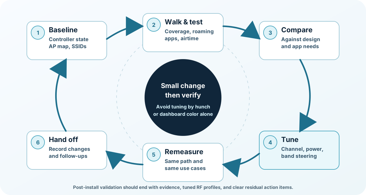
The key word is loop. Validation is not a one-pass walk with a scanner, and RF tuning is not a guess made from a controller dashboard. A good validation workflow starts with a baseline, walks the installed environment, compares evidence to the design intent, makes one bounded adjustment at a time, remeasures the same areas, and records what changed. That process keeps fixes from becoming new problems somewhere else in the building.
If you are still deciding which survey type is appropriate, start with PacketScout’s guide to predictive vs onsite WiFi surveys. If you need the commercial engagement that includes onsite measurement, heatmaps, and professional interpretation, see WiFi site survey services and WiFi heatmap services. This note stays focused on the validate-to-adjust loop after installation.
Why post-install validation is different from design
A wireless design is an informed model. It may include the floor plan, expected wall loss, AP models, antenna patterns, client counts, application needs, and a planned channel and power strategy. That model is useful, but it is not the same as the finished building. Real installations introduce details that are hard to model perfectly: APs mounted a few feet from the planned point, antennas tilted differently than expected, ceiling materials that were not visible on the drawing, furniture and shelving that changed after design, client devices with weaker radios, and neighboring networks that were not active during planning.
A validation survey checks the installed WLAN as a system. The surveyor is not only asking, “Is there signal?” The better question is, “Does this installed system support the intended users, devices, applications, and roaming paths with enough margin to survive normal business conditions?” That means the validation pass must look at coverage, channel reuse, airtime pressure, basic connectivity, roaming behavior, SSID/VLAN behavior, and whether controller automation is helping or hurting.
This is also where channel and power tuning becomes practical. Before installation, many channel and transmit-power settings are assumptions. After installation, you can see how cells overlap, whether APs hear each other too strongly, whether client devices are clinging to distant APs, and whether a low-signal area should be solved with RF tuning, an AP move, an antenna change, or an added access point. The right answer is not always “turn power up.” In dense networks, the right answer is often smaller cells, cleaner channel reuse, and less 2.4 GHz dependency.
The validation baseline: what to collect before walking
A clean validation pass starts before the first measurement is taken. Capture the installed state so any later RF change can be traced back to a known baseline. At minimum, the validation package should note the AP inventory, AP names, model types, installed locations, antenna types if external antennas are used, switch ports, PoE status, controller or cloud profile, SSIDs, VLAN mappings, security settings, band enablement, channel width, channel assignments, transmit-power state, and whether radio-resource management is automatic, manual, or constrained by profile limits.
The baseline should also identify the business areas that matter most. A warehouse aisle, exam room, classroom, conference area, guest lobby, manufacturing cell, and executive office do not all have the same tolerance for roaming delay or marginal signal. Treat validation as a set of use cases, not just a colored coverage map. If voice, video, barcode scanning, mobile point-of-sale, or roaming handhelds are part of the environment, the validation walk should include the paths those devices actually take.
Finally, confirm the version of the floor plan and AP map. Validation results are much less useful if the map does not match the installed access points. A surprising number of tuning discussions start with a basic mapping issue: the AP shown over a room is actually installed in the corridor, above a hard lid, inside a soffit, or in a different grid square. Fix the map before using the map to justify RF decisions.
The validate-to-adjust loop
A practical post-installation WiFi testing workflow has six steps.
1. Baseline the installed WLAN
Record the controller state and the physical installation. Save current channel, width, power, band, SSID, and AP-group settings before tuning. If the platform supports configuration snapshots or change history, capture that as well. The goal is not bureaucracy; it is rollback. RF tuning should be reversible, especially when the network is already in production.
2. Walk and test the real client paths
Run an onsite validation survey in the areas users actually occupy and travel through. Include static measurement points, normal roaming paths, application-specific tests, and areas where support tickets have already appeared. For many business networks, the most valuable walk is not the prettiest heatmap. It is the walk that follows a scanner from receiving to storage, a nurse from station to room, a tablet from lobby to conference room, or a voice handset through a stairwell and hallway transition.
3. Compare findings to design intent
Do not tune from one metric in isolation. Compare the evidence against the design goal for that space. A low-signal corner that has no business use may not matter. A marginal roaming transition on a route used by voice handsets may matter immediately. A busy AP is not automatically bad if it is carrying the intended users and there is clean airtime. An apparently green heatmap can still hide contention, retries, or sticky clients. For deeper RF theory around signal, noise, SNR, and channel overlap, use PacketScout’s WiFi signal, SNR, noise, and channel overlap guide as the owner page.
4. Make a bounded adjustment
Change one class of setting at a time where possible. Examples include narrowing a channel width in a dense area, reducing transmit power on a loud AP, moving a small group of APs to cleaner channels, disabling or reducing 2.4 GHz coverage in selected high-density areas, separating warehouse radios from office radios with different RF profiles, or adjusting band-steering/client-steering behavior when capable devices are not using the expected band. Bounded changes protect the rest of the network from unintended side effects.
5. Remeasure the same evidence
After the adjustment, repeat the relevant parts of the walk. Use the same problem area, same roaming path, same application test, and similar client device where practical. If the original issue was a roaming transition, do not validate only with a static signal reading. If the issue was channel congestion, do not validate only by checking that the controller accepted the new channel. RF tuning is complete only when the measured symptom improves without creating a new symptom nearby.
6. Document the final state and residual risks
The handoff should identify what changed, why it changed, what was remeasured, what remains at risk, and what should be watched after production load increases. This is where a professional report becomes useful, but the report deliverables themselves are owned by PacketScout’s professional WiFi site survey report guide. For this validation note, the important point is that tuning decisions should leave an audit trail.
Qualitative RF tuning decision table
Use this table as a decision aid, not as a universal prescription. The right action depends on client mix, application requirements, AP model, antenna pattern, regulatory domain, neighbor networks, and whether the design is coverage-led or capacity-led.
| Field symptom | Likely tuning direction | Validate by | Caution |
|---|---|---|---|
| Clients stay associated to distant APs while closer APs are available | Reduce excessive transmit power, review minimum rates and steering behavior, and check whether cells are too large | Repeat a roaming walk with representative clients and compare association changes | Do not make cells so small that coverage gaps appear between APs |
| Strong signal exists but performance is inconsistent in busy areas | Investigate airtime use, channel reuse, retries, channel width, and client distribution | Measure the same busy area during realistic load and compare utilization trends | A coverage map alone may look healthy while airtime is saturated |
| A dead spot remains after installation | Verify AP placement, mounting, antenna orientation, and obstruction; consider an AP move or added AP | Walk the exact affected area and confirm the improvement at client height | Raising transmit power may not fix the client uplink path |
| Many neighboring APs are heard on the same channel | Improve channel reuse, reduce cell size where appropriate, and avoid unnecessary wide channels | Compare channel overlap and client behavior before and after the change | Avoid chasing perfect separation in spaces where reuse is unavoidable |
| 2.4 GHz is overloaded or unstable | Prefer 5 GHz and 6 GHz for capable clients, reduce unnecessary 2.4 GHz SSIDs or radios, and protect required IoT devices | Test both modern clients and any 2.4 GHz-only devices that must remain supported | Do not break legacy or specialty devices by removing their only usable band |
| DFS or external interference events disrupt a cell | Recheck channel plan, local interference sources, and whether the band choice fits the environment | Correlate event history with user symptoms and field measurements | Moving every AP away from a band can create more congestion elsewhere |
| Voice, video, or scanner sessions drop during movement | Validate roaming boundaries, AP overlap, client drivers, authentication timing, and application behavior | Walk the actual route with the actual device class and active traffic | Roaming is a client decision; RF tuning helps but does not replace device testing |
| Controller automation keeps changing the problem area | Set practical guardrails, profile boundaries, or manual holds for the affected zone | Review change history and remeasure after the automation stabilizes | Full manual control can become stale if the environment changes later |
Mobile note: the table is intentionally scrollable on narrow screens so columns stay readable instead of squeezing into one-letter wrapping.
Channel, power, and band tuning principles
Post install RF tuning should be conservative and evidence-led. It is tempting to treat channel and power as two knobs that can fix everything, but each knob changes the shape of the network. Transmit power affects cell size, AP-to-AP overlap, client roaming decisions, and the balance between downlink and uplink behavior. Channel width affects airtime efficiency, available channel count, susceptibility to neighboring activity, and how many clean reuse opportunities exist. Band selection affects client capability, range, capacity, and compatibility with specialty devices.
When a network is under-covered, increasing transmit power may help only part of the conversation. The AP can shout louder, but the client may not be able to answer with the same strength. That is why validation must include client-side behavior. If the client uplink is the limiting factor, a power increase can make a map look better while the user experience remains poor. In that situation, the more durable fix may be an AP relocation, antenna change, or additional AP.
When a network is over-covered, the symptom can be more subtle. Users may technically have strong signal everywhere, yet performance is inconsistent because too many APs and clients contend in the same RF space. In that case, reducing power can improve the network by making cells more intentional. The goal is not weak coverage. The goal is useful overlap: enough for roaming and resilience, not so much that every AP hears every other AP at disruptive levels.
Channel planning also benefits from validation. Automatic radio-resource management can be valuable, but it is not magic. In complex buildings, it may need guardrails, AP groups, channel exclusions, or time to stabilize. Manual plans can also work, but they require discipline and documentation. The best choice depends on the environment. A small office, high-density classroom, warehouse, multi-tenant medical suite, and event space may need different levels of automation and segmentation.
Band tuning should reflect the actual client population. Modern laptops and phones should usually spend most of their time on 5 GHz or 6 GHz where the design supports it. That does not mean 2.4 GHz disappears. Many IoT, handheld, printer, badge, and specialty devices still depend on it. The validation pass should identify which devices must remain on each band, then tune band preference without breaking operational devices.
What a validation survey should not do
A validation survey should not become a second design project unless the installed network fails the basic assumptions. If the validation pass discovers that APs are in the wrong places, the floor plan is inaccurate, or the client requirements changed substantially, the right response may be a design correction rather than endless tuning. RF tuning can refine a good design; it cannot always rescue a bad installation.
It also should not duplicate every deliverable from a full site survey report. The validation package needs enough evidence to justify the tuning decision and support handoff, but it should not bury the owner in unrelated maps and exports. If the stakeholder needs a complete survey-report package, link the validation findings into the broader report format.
Finally, do not treat advanced WiFi 6 and WiFi 7 features as a shortcut around basic RF hygiene. Features such as BSS coloring can matter in dense modern WLANs, but they work best when channel reuse, power, and cell design are already sane. PacketScout’s WiFi 6E and WiFi 7 site survey guide is the better place for deeper feature planning.
When to bring in PacketScout
Post installation WiFi testing is most valuable when the network is close enough to work but not trustworthy enough to hand over. Common triggers include new AP deployments, controller migrations, office expansions, warehouse layout changes, complaints after a hardware refresh, intermittent voice/video issues, scanner drops, or a heatmap that looks acceptable while users still report problems.
PacketScout can help validate the installed WLAN, build heatmaps from measured data, interpret RF symptoms, and tune the network without turning every adjustment into guesswork. The deliverable is not just a map. It is a practical loop: measure the installed network, make the smallest useful RF adjustment, remeasure, and leave the owner with a clear final state and next actions.
If you are preparing for a post-install WiFi validation survey, gather the current floor plans, AP list, controller access for an authorized admin, known trouble tickets, client device types, and the business areas where WiFi cannot fail. That context makes the validation walk faster and the RF tuning decisions more defensible.